Rebar Inspection Checklist: 20 Checks Before Pouring Concrete
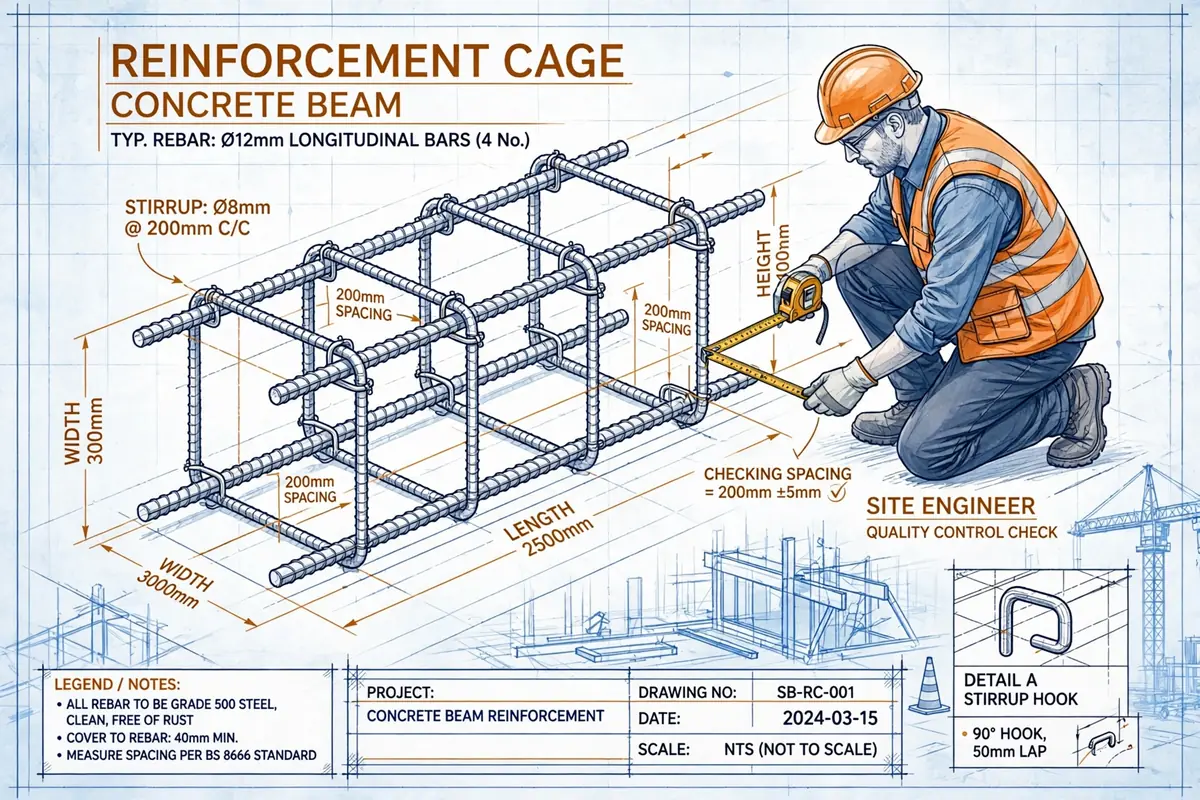
A practical site engineer's checklist for inspecting rebar work before concrete: cover, laps, spacing, ties and cleanliness, with code references and a worked example.
Once concrete is poured, your reinforcement is gone — buried inside the member for the life of the structure. That makes the hour before a pour the single most important quality checkpoint on any reinforced concrete job. Get the steel right and the concrete almost takes care of itself; miss a wrong bar size, a short lap, or zero cover, and you have a defect you can never fully fix.
This is the checklist I walk through on every pre-pour inspection, whether it is a footing, a beam, or a full slab. Work it top to bottom with the structural drawing in one hand and a tape in the other, and sign the pour card only when every item is ticked.
1. Check the steel against the structural drawing — not against memory
Start with the current drawing revision, not the one you remember from last week. Check the drawing number and revision against the BBS (bar bending schedule) the steel fixers worked from. I have seen columns cast with Y20 bars where the revision had upsized them to Y25 — caught it ten minutes before the pour, which was a very cheap catch and an expensive near-miss.
Verify bar mark numbers and shape codes (BS 8666) one mark at a time: diameter, number of bars, length, and bend shapes. A mark 4 beam stirrup that looks right but was bent as a 90-degree hook instead of a 135 will still sit in the beam — and it is still wrong.
2. Verify concrete cover everywhere, in every direction
Cover is the steel's only protection against fire, moisture, and corrosion. Too little cover and the bar corrodes and spalls the concrete; too much and you lose effective depth and crack control. Both are defects.
Typical nominal covers (IS 456 Table 16, and ACI 318 Table 20.6.1.3.1 in brackets):
- Footings cast against earth: 50 mm (IS 456) / 75 mm (ACI 318)
- Columns: 40 mm or bar diameter, whichever is greater
- Beams: 30 mm (IS 456) / 40 mm (ACI 318, interior)
- Slabs: 20 mm or bar diameter, interior exposure
- Concrete exposed to earth or weather (ACI): 50 mm for bars 20 mm and larger, 40 mm for smaller bars
For severe exposure (marine splash, chemical plants), IS 456 Table 16A raises these significantly — up to 75 mm in extreme conditions — so check the exposure class on the drawing, not just the member type.
On site, check that cover blocks or spacers are actually in place and the right size: no block, no cover. Walk the member and look for any bar touching formwork, blinding, or the ground. In footings, insist on precast concrete blocks — plastic chairs can creep and crush under a heavy cage.
3. Check bar spacing — minimum and maximum
Bars crammed too close together stop concrete and aggregate flowing between them, which is how you get honeycombing. Bars spread too far apart stop doing their job in the slab. Both limits are in the codes:
- Minimum clear spacing (IS 456 Cl 26.3.2 / ACI 318 Cl 25.2.1): at least the bar diameter, at least 25 mm, and at least 5 mm more than the maximum aggregate size. With 20 mm aggregate, that is 25 mm clear minimum between parallel bars.
- Maximum spacing in slabs (IS 456 Cl 26.5.3.2): main bars no more than 3 times the slab thickness or 300 mm, whichever is less; distribution bars no more than 5 times the thickness or 450 mm.
Run your tape across a slab mat at a few spots. Fixers tend to drift as they work — a 150 mm spacing that has wandered to 200 mm at the far end is one of the commonest things I flag.
4. Inspect laps: length, position and staggering
Lap length is not a guess — it equals the development length Ld (IS 456 Cl 26.2.5.1), calculated from bond stress:
Ld = φ × σs / (4 × τbd)
Here is a fully worked check for a 25 mm Fe500 column bar lapped in M25 concrete:
- Design bond stress for M25, τbd = 1.4 N/mm² (IS 456 Cl 26.2.5.1); for deformed bars multiply by 1.6 → τbd = 2.24 N/mm²
- Design steel stress, σs = 0.87 × 500 = 435 N/mm²
- Ld = 25 × 435 / (4 × 2.24) = 10,875 / 8.96 = 1,213 mm ≈ 1.21 m (about 50d)
So that 25 mm bar needs a 1.21 m lap minimum — and your tape measure is the only opinion that matters. Also check position: laps should be staggered so that not more than half the bars are lapped at any one section (IS 456 Cl 26.2.5.2), and keep laps away from zones of maximum stress where the drawing allows. Never accept laps in bars larger than 36 mm diameter without the designer's written approval.
5. Hooks, bends and anchorage
Every bar end on the drawing that shows a hook needs that hook, bent to the right angle, with the right extension. Standard anchorage values (IS 456 Cl 26.2.2.1): a standard 90-degree bend is worth 8 bar diameters of anchorage, a U-type hook 16 diameters. Per ACI 318 Table 25.3.2, a 135-degree seismic hook needs an extension of at least 6 bar diameters or 75 mm.
Check specifically: beam bars hooked into columns, slab bars into beams, and stirrup hooks closed at 135 degrees. An open 90-degree stirrup hook is a classic site shortcut that quietly destroys confinement — reject it every time.
6. Stirrups and links: spacing, size and first position
Verify stirrup diameter and spacing against the drawing, then check the first stirrup position: it should sit close to the support face, typically within 50 mm, not a full spacing away. Maximum spacing per IS 456 Cl 26.5.1.5 is the lesser of 0.75d and 300 mm. Quick site check for a 250 × 500 mm beam with 25 mm cover, 10 mm stirrups and 25 mm main bars:
- Effective depth d = 500 − 25 − 10 − 12.5 = 452.5 mm
- Maximum spacing = min(0.75 × 452.5, 300) = min(339, 300) = 300 mm
If the drawing calls for 250 mm spacing and you measure 320 mm on site, that is a fail — the shear design assumed 250. Also check that stirrups are vertical and that column links are at the specified pitch all the way up, including through the beam-column joint, where fixers love to skip them.
7. Tying: enough ties, in the right places, trimmed right
Binding wire (usually 16-gauge annealed wire) is cheap; failed laps are not. Demand 100% tying at every lap splice, at corners, and at bar intersections in beams and columns. In slabs, tying every other intersection in a staggered pattern is normally acceptable, but main bars at edges and around openings get tied at every intersection.
Then look at the tie ends: they must be twisted tight and bent inward, into the concrete — never left poking out toward the formwork, where the wire sits inside the cover zone and becomes a corrosion path straight to the bar.
8. Cleanliness of the steel
IS 456 Cl 7.1 is blunt: all reinforcement shall be free from loose mill scale, loose rust, paint, oil, mud, or any other deleterious matter. Light, tight mill scale that does not flake off is acceptable. What is not acceptable: flaky rust that comes off in your glove, form-release oil sprayed onto a fixed cage, mud splashed up by rain, or ice in cold weather.
Walk the cage and run a glove over suspect bars. Loose material gets wire-brushed off before the pour — it takes twenty minutes and removes the main cause of bond failure. Also check that nobody has used the cage as a welding earth or cut bars with a torch near the concrete face; both are instant rejects.
9. Alignment, level and straightness
Bars should be straight, slab mats level, and column bars plumb. Site damage is real: slab mats get walked on and sag between supports, column cages get knocked leaning when formwork goes up around them. A sagging top mat in a slab has lost effective depth exactly where the negative moment needs it most — lift it back onto chairs and re-tie it.
Check dowels and starter bars for the next pour too: correct diameter, correct projection length, in the right positions, and plumb. Fixing a misplaced starter after the concrete has set means drilling and chemical anchors, which nobody wants.
10. Chairs, spacers and cover blocks are doing their job
Top mats in slabs and beams need chairs at roughly 1 m centres to hold them at the right height under the weight of concrete and workers. Bottom cover blocks should be spaced so bars do not sag between them — about 1 m apart for typical slab bars, closer for heavy cages.
Step back and sight along the cage: if the top mat waves up and down, there are not enough chairs. In slabs, a quick string line across the top mat tells you in seconds whether it is level.
11. Formwork, openings and embeds interface
The steel does not exist in isolation. Confirm no bar is touching formwork anywhere — concrete cannot protect what it cannot surround. Check that openings are boxed out to the right size and position, that sleeves, conduits, and electrical boxes are fixed firmly enough to survive vibration, and that any cast-in plates or anchor bolts match the setting-out drawing. A sleeve that shifts during the pour becomes a core-drilling job later.
12. The final sign-off: the pour card
Nothing gets poured without a signed pour card. Mine lists: drawing number and revision, concrete grade and mix, estimated quantity, slump or workability class, cube moulds ready (typically 3 cubes per 7-day and 28-day test per sample), vibrators tested and a standby available, pump or crane access confirmed, weather checked, and the curing plan agreed — because the inspection does not end when the pour starts.
Get the reinforcement engineer (or whoever holds the design responsibility on your project) to sign alongside you. Two pairs of eyes, one signature each, zero ambiguity about who accepted the steel.
The 20 checks at a glance
Print this and carry it on a clipboard:
- 1. Drawing revision on site matches the steel fixed
- 2. Bar diameters match the BBS
- 3. Number of bars correct — main and distribution
- 4. Bar positions and layout match the drawing
- 5. Bend shapes and hooks per BS 8666 shape codes
- 6. Cover blocks/spacers in place, correct size
- 7. No bar touching formwork, blinding, or ground
- 8. Minimum clear spacing per IS 456 Cl 26.3.2 / ACI 318
- 9. Slab bar spacing within 3d/300 mm (main), 5d/450 mm (distribution)
- 10. Lap lengths equal Ld — measured, not eyeballed
- 11. Laps staggered, away from maximum-stress zones
- 12. Anchorage hooks present, correct angle and extension
- 13. Stirrup spacing within 0.75d/300 mm, first stirrup near support
- 14. 100% tying at laps and corners; tie ends bent inward
- 15. Chairs holding top mats level at ~1 m centres
- 16. Steel clean — no loose rust, oil, mud, or ice
- 17. Bars straight, plumb, level; no site damage
- 18. Dowels/starters correct, plumb, right projection
- 19. Openings, sleeves, and embeds fixed and positioned
- 20. Pour card signed: grade, quantity, cubes, vibrators, curing
A pre-pour inspection is not paperwork — it is the last moment in the entire construction process when the most important part of a concrete member is still visible. Walk the checklist, measure what can be measured, reject what fails, and pour with confidence.
Calculations and engineering guides are for planning and educational reference. Verify final designs against applicable codes with a licensed Professional Engineer.