Levels and Grids in Revit: First Project Setup Guide
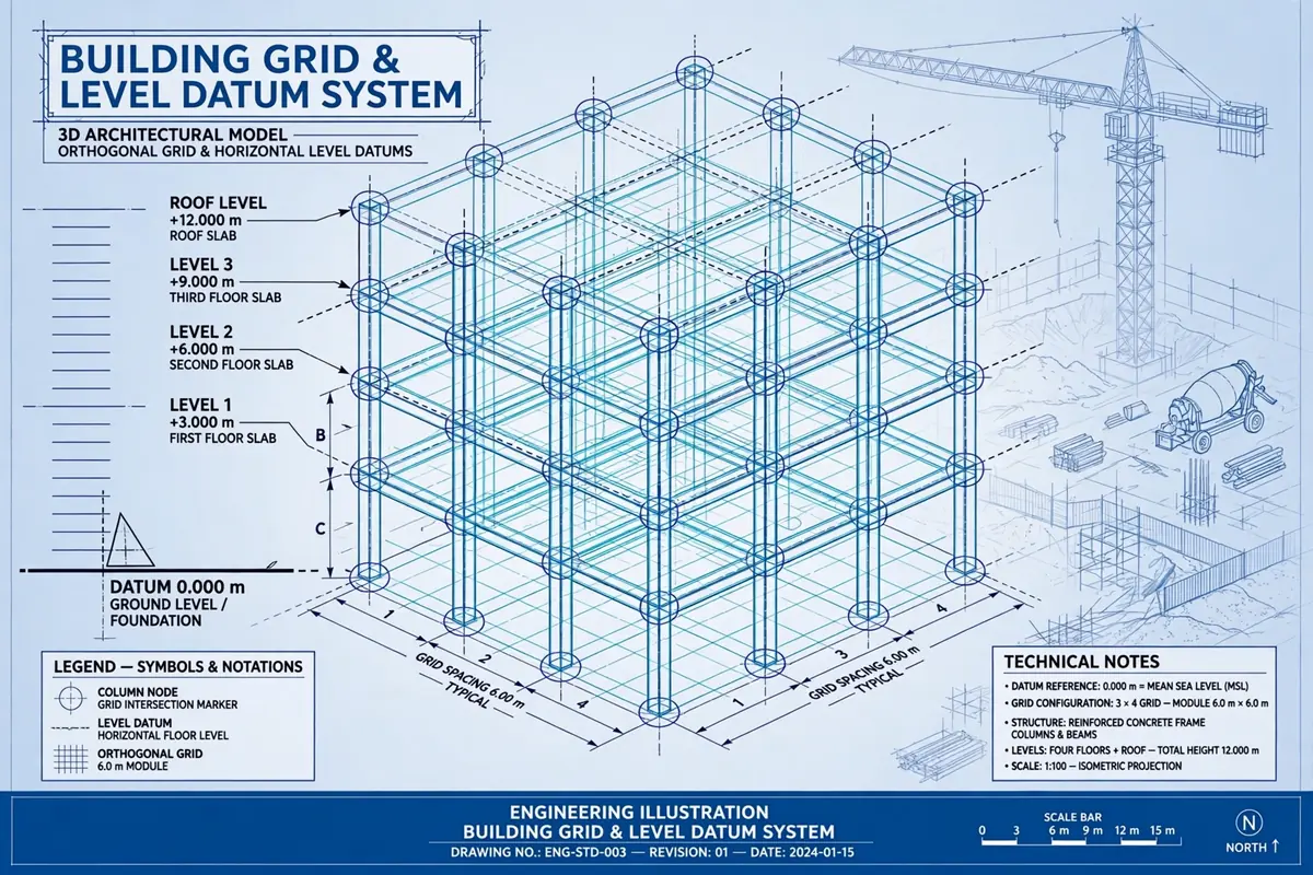
Learn to set up levels and grids in Revit for your first project: naming, spacing, scope boxes, and a worked grid layout for a small building.
Ask any experienced Revit user what they set up first on a new project, and the answer is almost always the same: levels and grids. Not walls, not rooms, not a fancy facade. Levels and grids come first because almost everything else in the model hangs off them. A wall is placed on a level, a column sits at a grid intersection, a floor is hosted by a level, and a section cut is read against those same datums. Get them wrong on day one and you will spend the rest of the project chasing small errors that refuse to stay fixed.
This guide walks through a clean first-project setup in Revit: what levels and grids actually are, how to create them properly, how to name them so a contractor can read them, and a fully worked grid layout for a small building. The example uses metric units, but the logic is identical if you work in feet and inches.
What levels are in Revit
A level in Revit is a horizontal datum plane. Think of it as an invisible floor plate stretching infinitely in every direction at a fixed height. When you draw a wall and set its base constraint to Level 1 and its top constraint to Level 2, you are not just typing in heights — you are telling Revit that the wall belongs to those two datums. Move Level 2 up by 300 mm later, and every element hosted to it moves with it.
That is the real power of levels, and also the trap. If you model with hard-typed heights instead of level constraints, a late change in floor-to-floor height becomes a manual edit on dozens of elements. If you model to levels, it becomes one edit. This is why senior modellers are so strict about it: host to levels, never to typed offsets, unless you have a specific reason not to.
What grids are in Revit
Grids are the vertical datum planes that define the building's structural layout in plan. In a typical reinforced concrete frame, grids run in two directions: one set across the width of the building, the other along its length. Columns, walls and beams are then located by grid intersection — for example, column C3 sits where grid C meets grid 3.
By convention, one direction is lettered and the other is numbered. In most offices, numbers run along the longer direction and letters across the shorter one, but the important thing is consistency within a project, not which way round you choose. Grid bubbles appear at the ends of each grid line, and those bubbles are what the contractor reads on site. A grid that is visible in one view but hidden in another is a common source of confusion, so grid visibility is controlled per view and must be checked on every sheet, not just in the working plan.
Before you draw anything: template, units and origin
Start from the right template. For building work, the default architectural template is a sensible starting point for a first project; a structural template is better if the model is primarily a frame. Either way, check the units before you place a single level: Manage > Project Units, length in metres or millimetres, and decide now whether you will work in metres (0.000 m) or millimetres (0 mm). Mixing the two in your head is how 300 mm errors happen.
Next, settle the origin. Revit has two related but different points: the Project Base Point and the Survey Point. For a first project, the practical rule is simple. Put the Project Base Point at a sensible local origin — often grid intersection A1 — and leave the Survey Point alone unless you are coordinating with a surveyor's real-world coordinates. Do not drag either point around casually; moving the base point shifts how every shared coordinate is reported. If you are unsure, leave both at the template defaults and set your grids relative to them.
Step-by-step: creating levels
Open an elevation view — south or east is fine — and use Architecture > Datum > Level, or the equivalent structural datum tool. Click to place the level line, then click its elevation value and type the height. Work from the ground up, and name each level as you go rather than leaving a string of Level 1, Level 2, Level 3 with no meaning.
- Ground floor: set this to 0.000 m and treat it as your project datum. Everything else is measured from here.
- Upper floors: add the floor-to-floor height each time. A typical residential or small commercial floor-to-floor height is 3.000 m to 3.600 m, measured from finished floor to finished floor, not from slab soffit.
- Roof: add a roof level at the top of the highest floor, plus a parapet or roof plant level only if the design actually needs one. Extra levels that nothing is hosted to just clutter the browser.
- Basement or plinth: if the building has a basement, add it below ground with a negative value, for example −3.000 m, and check that its plan view is created too.
Step-by-step: creating grids
Switch to a floor plan view and use Architecture > Datum > Grid. Click once to start the line and once to end it, extending it slightly beyond the building on both ends so the bubbles sit clear of the walls. Then use the Copy or Array approach with a typed distance to place the parallel grids, rather than clicking each one by eye. Eye-balled grids are how a 6.000 m bay quietly becomes 5.987 m.
For a rectangular building, place one direction first — say the lettered grids across the width — then the numbered grids along the length. After placing them, click each bubble and check its label: Revit auto-numbers grids, but it will happily give you 1, 2, 3, 4 in an order you did not intend if you drew them right to left. Reorder or rename bubbles until the sequence reads sensibly from one side of the building to the other.
Worked example: a small 24 m by 15 m building
Suppose you are setting up a small three-storey concrete frame building, 24.000 m long and 15.000 m wide, with a regular column grid. This is the kind of exercise a junior draughtsman is given on their first week, and it is worth doing by hand before you trust the software to do it for you.
Grid layout
Across the width, use lettered grids A, B, C and D. That gives three bays. Divide 15.000 m by 3 bays:
15.000 m ÷ 3 = 5.000 m per bay. So grid A is at 0.000 m, grid B at 5.000 m, grid C at 10.000 m and grid D at 15.000 m.
Along the length, use numbered grids 1 to 5. That gives four bays. Divide 24.000 m by 4 bays:
24.000 m ÷ 4 = 6.000 m per bay. So grid 1 is at 0.000 m, grid 2 at 6.000 m, grid 3 at 12.000 m, grid 4 at 18.000 m and grid 5 at 24.000 m.
The total number of grid intersections — and therefore the maximum number of column positions — is the product of the two counts:
4 lettered grids × 5 numbered grids = 20 grid intersections. On a real project you would not necessarily put a column at every intersection; edge columns, corner columns and internal columns are decided by the structural engineer. But the grid itself is complete at 20 intersections, and every column you do place can be described unambiguously, such as column C3 at the intersection of grid C and grid 3.
Level heights
Take a floor-to-floor height of 3.300 m. Starting from the ground datum:
- Ground Floor: 0.000 m
- Level 1: 0.000 m + 3.300 m = 3.300 m
- Level 2: 3.300 m + 3.300 m = 6.600 m
- Roof: 6.600 m + 3.300 m = 9.900 m
The total building height to roof level is therefore 9.900 m, before any parapet. If the architect later raises the floor-to-floor height to 3.600 m, you change one value per level — or better, you adjust the level elevations and let every hosted wall, column and floor follow. The recomputed roof level would be 3 × 3.600 m = 10.800 m, a 900 mm change that would be miserable to apply by hand across a whole model.
Naming, scope boxes and visibility
Scope boxes are the tool that stops levels and grids appearing where they should not. A scope box is a 3D box that controls which datums are visible in the views it is applied to. For a first project you may not need one, but as soon as you have a part of the building with its own levels — a split-level section, a plant room, a tower — a scope box is how you keep those datums out of the main plans. Apply scope boxes deliberately, view by view, and check a sheet before issuing it.
Common mistakes on a first project
- Modelling to typed heights instead of levels. Everything looks right until the floor height changes, and then nothing moves together.
- Two levels at almost the same height. A level at 3.300 m and another at 3.301 m, created by accident, will produce duplicate plan views and walls that refuse to join cleanly.
- Grids drawn by eye. A bay that is 5.987 m instead of 6.000 m will pass unnoticed in plan and fail on a dimension check.
- Grid bubbles on the wrong side. Bubbles should read consistently around the building; a bubble flipped to the inside of the plan confuses anyone reading the drawing.
- Moving a grid after issue. Once a grid is on an issued drawing, moving it renumbers columns on site. If a grid must move, do it through a formal revision, not a quiet drag.
- Forgetting the roof level. Walls drawn up to “Level 2” with a typed offset instead of to a roof level will not follow a roof change.
Checklist before you start modelling
Run through this list before you draw a single wall. It takes two minutes and prevents most first-project rework:
- Template and project units confirmed, in metres or millimetres, and used consistently.
- Ground floor level at 0.000 m, with every upper level named and spaced by the correct floor-to-floor height.
- Every level has a floor plan view, and each plan shows the expected level.
- Grids in both directions, lettered one way and numbered the other, with equal bays checked by division.
- Grid bubbles visible and on the correct side in the plan views you will draw in.
- Project Base Point at a sensible origin, Survey Point untouched unless coordinating with survey data.
- Project north pointing up, building drawn square to the screen.
Do that, and the rest of the model has something solid to stand on. Levels and grids are not glamorous work, and nobody will praise a tidy datum setup on its own. But a model built on clean datums is a model that can be changed, checked and issued without fear — and that is the whole point of working in Revit rather than drawing lines. For a broader view of where Revit fits against 2D drafting, see the companion guides on setting up units, limits and layers for structural drawings, and on choosing between Revit and AutoCAD for a given task.
Calculations and engineering guides are for planning and educational reference. Verify final designs against applicable codes with a licensed Professional Engineer.