Levelling Basics: Datum, Benchmarks and Reduced Levels
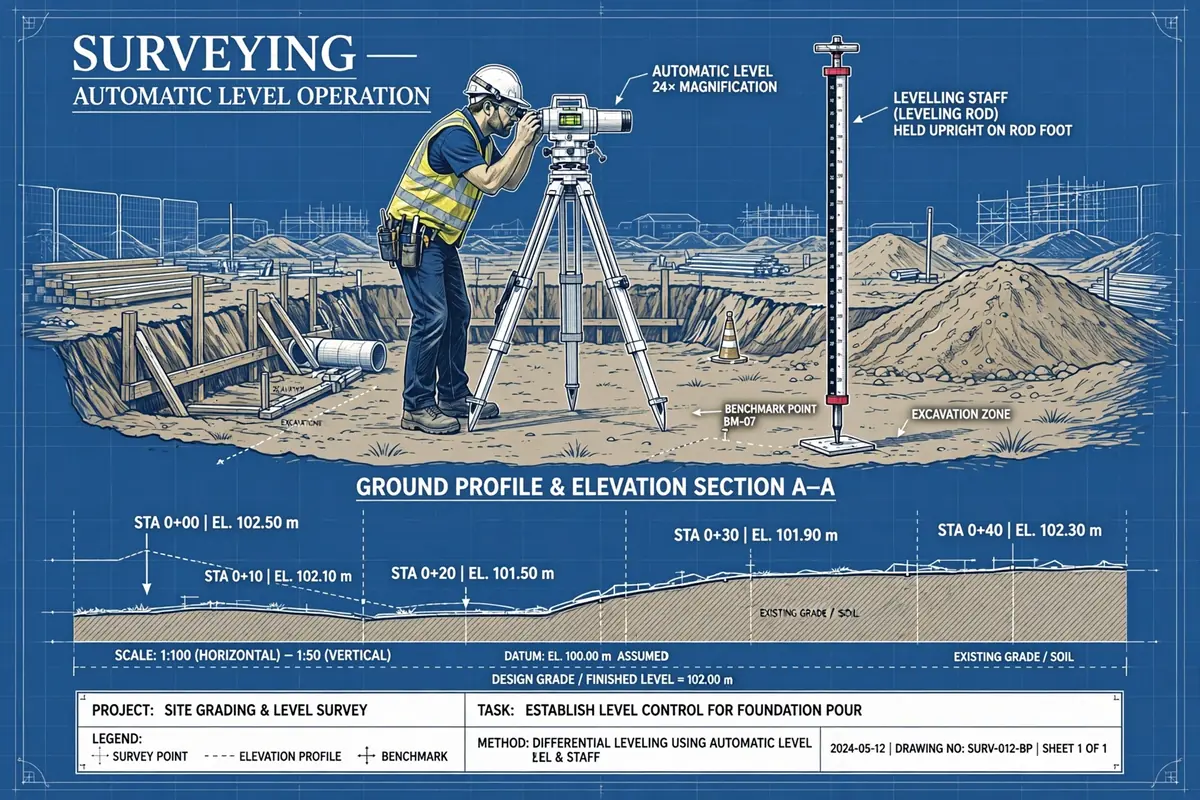
Levelling basics explained: datums, benchmarks and reduced levels, with a worked height-of-instrument example any junior site engineer can follow.
Ask a surveyor what a site is really built on and they will not say concrete or steel. They will say levels. Every foundation depth, floor slab, road gradient and drainage fall on a project is measured from one thing: a height above a known reference point. Get that reference wrong, or misunderstand how it is carried across a site, and a building can end up 300 mm too high, a drain can run backwards, and nobody will notice until the concrete is already in the ground.
This guide covers the three ideas every junior engineer must be comfortable with before they ever look through a level instrument: datum, benchmarks and reduced levels. They sound like textbook terms, but on site they are practical tools you will use every single day.
What Is a Datum?
A datum is simply the zero point from which all heights on a project are measured. Think of it as the ground floor of your height system — everything else is quoted as so many metres above or below it.
On most national surveys the datum is mean sea level (MSL). In the UK, for example, heights are quoted above Ordnance Datum Newlyn, the mean sea level measured at Newlyn in Cornwall between 1915 and 1921. In the United States the reference is NAVD88. Your country's survey department will have its own equivalent, and any drawing that quotes a level without saying which datum it uses is incomplete.
But on a small building site, tying into national MSL is often unnecessary. Instead, the surveyor adopts an assumed datum: a convenient local value, often 100.000 m, assigned to a fixed point on site. This keeps all reduced levels positive and easy to work with, which matters when you are doing arithmetic in the field. The only rule is that the assumed datum must be written on every drawing and level book page. A level of 102.450 m means nothing if nobody knows what it is 102.450 m above.
One thing to be clear about: a datum is a surface, not a peg in the ground. The peg in the ground is a benchmark — and that is where the confusion usually starts.
Benchmarks: The Fixed Points You Can Trust
A benchmark (BM) is a physical, permanent mark whose height above the datum is known. It is the anchor for every level run on the job. Common types include:
- Ordnance benchmarks (OBM): cut marks or brass plaques on permanent structures such as bridges, culverts and public buildings, established by the national survey authority. Their published heights are the most reliable reference you will find.
- Temporary benchmarks (TBM): marks set up by the site surveyor for the duration of the project — a nail in a concrete plinth, a bolt in a kerb, a peg protected by a small concrete surround. A TBM is only as good as its protection: a TBM next to a haul road will not survive the first week of tipper traffic.
- Fundamental benchmarks: deep, stable marks maintained by national agencies, used as the backbone of the whole country's height network.
Two rules govern benchmarks on site. First, never work from a single benchmark. Establish at least two, checked against each other, so that if one is disturbed you can prove it rather than guess. Second, never assume a benchmark is still at its published height. A benchmark on a retaining wall that has moved, or a TBM on ground that has been recompacted, will quietly corrupt every level taken from it. Re-check your TBMs regularly, especially after heavy rain or nearby excavation.
Reduced Levels Explained
A reduced level (RL) is the height of a point above the datum, after all the instrument readings have been "reduced" — that is, converted from raw staff readings into proper heights. The word "reduced" here has nothing to do with making something smaller; it is surveyor's language for working out the final figure.
Here is the logic. A level instrument sets up a perfectly horizontal line of sight. When you look through it at a vertical staff held on a point, the reading tells you how far below that line of sight the point sits. If you know the height of the line of sight itself, you can find the height of the point:
RL of a point = Height of instrument (HI) − staff reading
And the height of the instrument comes from a point whose RL you already know — your benchmark:
HI = RL of benchmark + backsight reading on the benchmark
That is the entire theory. Everything else in levelling is bookkeeping to carry this calculation across many points and many instrument setups without losing accuracy.
The Language of a Level Run: Backsight, Foresight, Intermediate Sight
Three terms describe every staff reading you will ever take:
- Backsight (BS): the first reading taken after setting up the instrument, on a point of known RL — usually your benchmark. It is called a backsight because you are looking "back" to a known point, not because of the direction you face.
- Foresight (FS): the last reading before moving the instrument, on a point whose RL you want to fix — often the next change point or the final point of the run.
- Intermediate sight (IS): any reading in between, on points whose levels you need but which do not anchor the next setup.
A change point (CP) is a firm, stable point where you take a foresight, move the instrument, and then take a backsight on the same point from the new position. Change points are how a level run travels across a site. Always choose change points that will not move between the two readings — a manhole cover, a concrete plinth, a solid kerb — never soft ground or a loose brick.
Worked Example: Height of Instrument Method
Let us run a small level traverse. The site uses an assumed datum, and a TBM near the site entrance has an RL of 100.000 m.
Setup 1. The instrument is set up and a backsight is taken on the TBM: BS = 1.425 m.
HI = 100.000 + 1.425 = 101.425 m.
From this setup, three readings are taken:
- Intermediate sight on the proposed floor slab corner: IS = 0.860 m → RL = 101.425 − 0.860 = 100.565 m
- Intermediate sight on the invert of an existing drain: IS = 2.210 m → RL = 101.425 − 2.210 = 99.215 m
- Foresight on change point CP1 (a manhole cover): FS = 1.640 m → RL = 101.425 − 1.640 = 99.785 m
Setup 2. The instrument moves. A backsight is taken on CP1: BS = 1.105 m.
New HI = 99.785 + 1.105 = 100.890 m.
A foresight is taken on the far corner of the plot: FS = 0.745 m → RL = 100.890 − 0.745 = 100.145 m.
Now the arithmetic checks, which you must do before leaving site. The sum of backsights minus the sum of foresights must equal the difference between the first and last RL:
ΣBS − ΣFS = (1.425 + 1.105) − (1.640 + 0.745) = 2.530 − 2.385 = 0.145 m
Last RL − First RL = 100.145 − 100.000 = 0.145 m. The check closes.
If these two figures do not match, there is a booking or arithmetic error somewhere in the run. Find it before you pack up — going back the next day to re-run a level traverse is the kind of mistake that earns you a reputation fast.
Closing the Loop: Why You Always Come Back
A level run that ends at a new point proves nothing about its own accuracy. The professional habit is to close the loop: run back to your starting benchmark, or forward to a second known benchmark, and compare the RL you get with the RL you started from. The difference is the misclosure.
For ordinary construction work, a misclosure of a few millimetres over a few hundred metres is normal. A common allowable limit is 12√K mm, where K is the distance levelled in kilometres — so over 0.25 km, about 6 mm. If your misclosure is larger, the run is suspect and must be repeated. Never "adjust" a bad misclosure away by fudging readings. The whole point of the check is to catch errors, and a hidden error will surface later in the most expensive way possible.
Common Errors That Catch Beginners
- Staff not vertical: a staff leaning even slightly reads high, because the line of sight hits a higher graduation. The staff holder should rock the staff gently fore and aft and the observer takes the minimum reading.
- Parallax: if the crosshairs and the staff image are not in the same plane, the reading shifts as your eye moves. Focus the eyepiece on the crosshairs first, then focus on the staff, until moving your head does not move the reading.
- Instrument not level: modern automatic levels compensate for small tilts, but they have limits — typically a few minutes of arc. Level the circular bubble properly every time.
- Booking errors: writing a backsight in the foresight column, transposing digits, or forgetting a change point. Book neatly, in the field, in pencil — never from memory at the site office.
- Settlement of the tripod or change point: on soft ground, the instrument or the staff can sink between readings. Use firm change points and keep setups short.
- Curvature and refraction: over long sights the earth's curvature and atmospheric refraction bend the line of sight. For ordinary site work with sights under 100 m, the effect is negligible, but keep backsight and foresight distances roughly equal so the errors cancel.
From Levels to Setting Out
Once you can run levels confidently, the same skill drives everything else on site. Floor levels are set from a TBM with a staff and a level. Excavation depths are checked by taking a reading on the formation and subtracting from the design formation level. Drainage falls are verified by comparing invert levels at each manhole — a 150 mm pipe laid at 1 in 100 falls 10 mm every metre, and a 20 mm levelling error can halve or double that gradient.
That is why surveyors are so particular about benchmarks and bookwork. The levels you hand to the foreman become the building. Treat the datum with respect, protect your benchmarks, check your arithmetic in the field, and close every run. The rest of levelling is practice.
Quick Reference
- Datum: the reference surface (often MSL, or an assumed local value such as 100.000 m) from which all heights are measured.
- Benchmark: a permanent mark of known height above the datum; work from at least two and re-check them.
- Reduced level (RL): the height of a point above the datum.
- HI = RL of known point + backsight. RL of any point = HI − its staff reading.
- Check: ΣBS − ΣFS must equal last RL − first RL. Close every run back to a known point.
Calculations and engineering guides are for planning and educational reference. Verify final designs against applicable codes with a licensed Professional Engineer.