Concrete Cover Requirements: Footings, Columns, Beams, Slabs
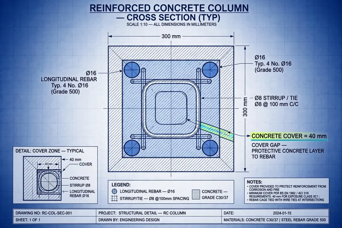
ACI 318 minimum concrete cover for footings (3 in.), columns, beams (1.5 in.) and slabs (3/4 in.), with worked cover and effective-depth calculations.
Every reinforcement drawing you will ever read carries a small dimension that is easy to overlook and expensive to get wrong: concrete cover. It is the distance from the outside face of the concrete to the surface of the nearest steel. Get it too thin and the steel corrodes, spalls the concrete, and the member loses strength decades early. Get it far too thick and you have eaten into the effective depth of your beam or slab, silently reducing the capacity you calculated on paper. Cover is where durability design meets site reality, and ACI 318 treats it as a hard minimum — not a target.
What "cover" actually measures
Cover is measured from the outer concrete surface to the outermost face of the nearest reinforcement — and that includes the ties, stirrups, and spirals, not just the main bars. This is the mistake junior engineers make most often: they dimension cover to the longitudinal bars, forget the No. 4 tie wrapping around them, and end up short by a full bar diameter. ACI 318 Section 20.6 defines specified cover to the outer reinforcement. If your column has No. 9 verticals with No. 4 ties at 1-1/2 in. cover, the cage as a whole sits 1-1/2 in. from the form — the ties, not the verticals, set the position.
Cover does three jobs at once: it keeps aggressive agents (chlorides, carbonation, moisture) away from the steel, it shields the steel in a fire, and it provides the concrete around each bar that bond and development length rely on. That is why the code minimums exist and why inspectors treat a short cover reading as a defect, not a rounding error.
The ACI 318 cover table, in plain English
ACI 318-19 Table 20.6.1.3.1 gives minimum specified cover for cast-in-place concrete. The logic runs on exposure: the nastier the environment, the thicker the shell. Here is the table translated for site use:
- Concrete cast against and permanently in contact with the ground (footings, pile caps, grade beams poured against soil): 3 in. — no exceptions. This is the one that fails inspection most often, because soil is never perfectly flat and bars sink into it.
- Concrete exposed to weather or in contact with the ground: No. 6 bars and larger (including No. 14 and No. 18) get 2 in.; No. 5 and smaller get 1-1/2 in.
- Concrete NOT exposed to weather or in contact with the ground (interior members): beams and columns get 1-1/2 in. to ties, stirrups, and spirals; slabs, walls, and joists get 1-1/2 in. for No. 14 and No. 18 bars and 3/4 in. for No. 11 bars and smaller.
Notice the pattern: the harsher the exposure, the thicker the cover, and bigger bars need more cover because a bigger bar presents a bigger corrosion front and needs more concrete around it to develop bond.
Footings: the 3-inch rule and why it is absolute
A footing is cast against soil that is wet, uneven, and full of things that attack steel. ACI 318 gives it the maximum cover — 3 in. — and there is no reduction, no "close enough." On site, the enemy is the cage sinking into soft subgrade or sitting on a mound of dirt. A bar that rests directly on soil has zero cover.
This is also where the topic of bar supports gets serious. Plastic chairs are fine for a slab on a deck, but for a footing mat sitting on soil, use precast concrete blocks or manufactured concrete "dobies" as supports — plastic chairs creep under load and can crush into soft ground, and steel chairs corrode from the bottom up, both of which silently steal your 3 in. Concrete blocks bond with the pour and hold the mat exactly where you set it. Place them on a roughly levelled, compacted blinding or directly on firm undisturbed soil at spacings that keep the mat from sagging between supports — typically every 3 to 4 ft in each direction for a footing mat, closer if the soil is soft.
One more site habit worth building: after the mat is set, walk the footing with a tape before the pour and check the actual cover in a few spots. If a bar has slipped off a block, fix it then — concrete is not a corrector of position.
Columns and beams: 1-1/2 inches to the tie
For cast-in-place columns and beams not exposed to weather, ACI 318 requires 1-1/2 in. of cover — measured to the tie, stirrup, or spiral, since those are the outermost steel. Two consequences fall out of this:
- Column cage sizing: the cage outside dimension equals the column dimension minus twice the cover. A 24 in. × 24 in. column with 1-1/2 in. cover gets a tie cage 21 in. × 21 in. outside-to-outside. The longitudinal bars then sit inside the ties, at 1-1/2 in. + tie diameter from the face.
- Beam effective depth: the cover, stirrup diameter, and half a main-bar diameter all stack up between the beam soffit and the centroid of the tension steel. Every extra half inch of cover you place is a half inch less effective depth — and moment capacity scales with the square of effective depth, so cover creep costs real capacity.
For beams and columns exposed to weather — an exterior frame, a parking structure — the cover steps up to 2 in. for No. 6 bars and larger, 1-1/2 in. for No. 5 and smaller. Check the exposure condition on the drawing before you accept the bar bending schedule's cage sizes; weather exposure is the silent change that rewrites every cage dimension.
Slabs and walls: the thin members
Interior slabs and walls get the smallest covers — 3/4 in. for No. 11 bars and smaller — because they live in a benign environment and because a thick slab pour cannot spare the depth. A 3/4-in. cover is a thin margin, though, and it demands discipline: support the top mat on chairs at proper spacing so it cannot sink during the pour and vibration, and keep the bottom mat off the form on chairs, not on offcuts of timber.
For slabs on grade exposed to weather or in contact with the ground, the cover rises to the weather-exposure row: 1-1/2 in. for No. 5 bars and smaller, 2 in. for No. 6 and up. And a slab cast directly against earth without a membrane is in the footing category — 3 in., same as a footing.
Worked example 1: sizing a column cage from the cover requirement
Take a 20 in. × 20 in. interior column with 8 No. 8 longitudinal bars and No. 4 ties, 1-1/2 in. specified cover. What is the tie cage size, and how far is each longitudinal bar from the column face?
Step 1 — cage outside dimension. Cover is measured to the ties, the outermost steel:
Cage size = 20 − 2 × 1.5 = 17 in. × 17 in. outside-to-outside of ties.
Step 2 — distance to the longitudinal bars. A No. 4 bar has a diameter of 0.500 in. The face of each No. 8 bar sits one tie diameter inside the cover line:
Cover to main bars = 1.5 + 0.500 = 2.0 in. from the concrete face.
Step 3 — sanity check on the tie legs. The fabricator bends the No. 4 ties to 17 in. outside dimension. When the cage goes up, a tape check from form face to tie should read 1-1/2 in. on all four sides. If it reads 1 in., the cage is wrong — or the form moved — and the pour waits until it is fixed. That five-minute check is the whole inspection philosophy of cover in one gesture.
Worked example 2: how cover sets beam effective depth
Take a 12 in. wide × 20 in. deep interior beam, reinforced at the bottom with 3 No. 9 bars in one layer and No. 4 stirrups, 1-1/2 in. cover. The designer needs the effective depth d — the distance from the extreme compression face (top of beam) to the centroid of the tension steel.
Step 1 — stack the distances from the soffit. A No. 9 bar is 1.128 in. in diameter; a No. 4 stirrup is 0.500 in.:
Distance to steel centroid = cover (1.5) + stirrup diameter (0.500) + half bar diameter (1.128 / 2 = 0.564) = 1.5 + 0.500 + 0.564 = 2.564 in., say 2.56 in.
Step 2 — effective depth:
d = 20 − 2.56 = 17.44 in.
Now the punchline: suppose the steel fixer is generous and places the cage with 2-1/2 in. of clear cover instead of 1-1/2 in. — an extra inch that "feels safer." Effective depth drops to 16.44 in. Moment capacity is proportional to d², so the capacity ratio is (16.44 / 17.44)² = 0.889 — an 11% loss of bending capacity from one inch of extra cover. Too little cover corrodes; too much cover weakens. The drawing's number is not a suggestion.
Tolerances: what ACI 117 allows
Site placement is never perfect, and ACI 117 recognises that. The tolerance on cover is negative — it tells you how far short you may fall, not how far over you may go. For typical members the permitted shortfall is on the order of 1/4 to 3/8 in., depending on member depth. The practical reading: detail and place to the full specified cover, and treat anything more than a small shortfall as a defect to correct.
There is an asymmetry worth remembering. ACI 318's cover values are minimums. Being 1/2 in. over on a column is harmless; being 1/2 in. under is a durability defect. But on a beam or slab, being well over eats effective depth, as the example above showed. The safe zone is narrow by design: place it right, check it, pour.
Cover and fire rating
Cover is also the first line of fire protection. In a fire, the concrete around the steel is insulation — the thicker the cover, the longer the steel stays below the temperature where it loses strength (around 1000°F / 540°C). ACI 216.1 and the IBC give required cover for fire-resistance ratings, and for rated members the fire cover often exceeds the durability cover — a 2-hour rated beam may need 2 in. or more where durability alone asked for 1-1/2 in. When the drawings show a fire rating, the governing cover is the larger of the two. Always check.
Pre-pour cover checklist
- Confirm the exposure condition (interior, weather-exposed, or cast against earth) — it selects the cover row.
- Verify cage dimensions against cover measured to ties and stirrups, not to main bars.
- Footings and earth-contact concrete: 3 in. cover on concrete block supports — no plastic chairs, no steel chairs sitting on soil.
- Slabs: chairs under both mats, at spacings that survive the pour and the vibrator.
- Spot-check with a tape in several locations; fix slipped bars before concrete arrives.
- Check that fire-rating requirements do not demand more cover than the durability table.
Quick reference
- Cast against earth (footings, pile caps): 3 in. — concrete block supports, no exceptions.
- Weather-exposed or ground-contact: No. 6 and larger — 2 in.; No. 5 and smaller — 1-1/2 in.
- Interior beams and columns: 1-1/2 in. to ties/stirrups.
- Interior slabs, walls, joists: No. 14/18 — 1-1/2 in.; No. 11 and smaller — 3/4 in.
- Measured to: the outermost steel, including ties and stirrups.
- Fire rating: may govern over the durability cover — take the larger.
Cover is a small number with large consequences. It is the cheapest durability measure in the whole structure — a few well-placed concrete blocks and a tape check — and the most commonly skipped inspection item on site. Place it right, check it before the pour, and the steel stays protected for the life of the building.
Calculations and engineering guides are for planning and educational reference. Verify final designs against applicable codes with a licensed Professional Engineer.