BIM Basics for Site Engineers: What Changes on Site
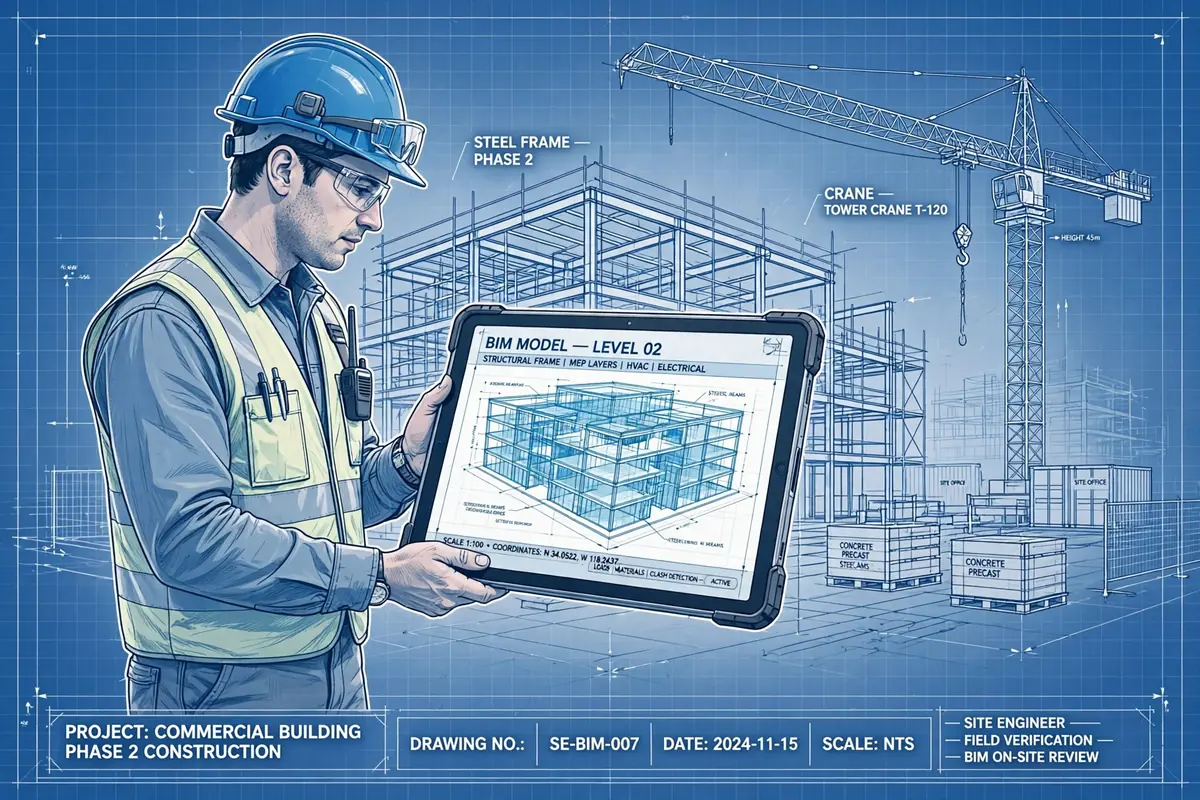
BIM changes how drawings are made, clashes are found and site work is checked — a practical guide for site engineers on models, clash detection and 4D planning.
If you have spent any time on site in the last few years, you will have heard the term BIM — Building Information Modelling — thrown around in meetings, usually by someone in the design office who has never stood in a muddy excavation. It is easy to dismiss it as another piece of software jargon. That would be a mistake. BIM changes the way drawings are produced, the way clashes are found, and the way you, as the site engineer, check work, order materials and record what was actually built. This article explains what BIM really is, in plain site language, and what actually changes for you on the ground.
What BIM Actually Is (and Is Not)
BIM is not a software package, and it is not just a 3D drawing. It is a way of working where every part of a building — every column, beam, wall, duct and pipe — exists once, as a smart object, inside a single coordinated model. A column in the model is not just a rectangle on a plan. It knows its size, its concrete grade, its reinforcement, its pour sequence and its cost. Change the column size in the model, and every plan, section, elevation and schedule that shows that column updates automatically.
Compare that with the traditional 2D workflow you know well. The architect draws a plan, the structural engineer draws a separate framing plan, and the services engineer draws yet another set of drawings. Each team works from its own files, and coordination happens by overlaying drawings and hoping someone spots the beam that runs straight through an air-conditioning duct. On a BIM project, all disciplines build their part of the same model, so those conflicts surface on a screen weeks before anyone orders steel.
The model also carries information beyond geometry. The industry shorthand for this is dimensions: 3D is the geometry, 4D adds time (the construction programme linked to model elements), 5D adds cost (quantities priced from the model), 6D covers sustainability, and 7D is the facilities-management data handed to the building owner. As a site engineer, you will mostly live in 3D, 4D and 5D.
The Common Data Environment: One Source of Truth
Every BIM project runs on a Common Data Environment (CDE) — a single online platform where the current model and all documents live. The old habit of working from a drawing revision emailed three weeks ago, or from a printout pinned in the site cabin, is exactly what the CDE is designed to kill. Drawings in the CDE carry a status: Work in Progress, Shared, Published, or Archived. You should only ever build from Published information.
That sounds obvious, yet a large share of site rework still comes from building to superseded drawings. On a BIM job, the rule is simple and worth enforcing ruthlessly: if it is not the published revision in the CDE, it does not get built. Before every pour, check the revision number in the CDE against the drawing on the gang's table. It takes thirty seconds and it saves entire weekends of breakout work.
Clash Detection: Finding Problems Before They Cost Money
The single biggest practical benefit of BIM on site is clash detection. Software compares the architectural, structural and services models and flags every place where two objects occupy the same space, or come closer than the allowed clearance. A classic example: a 300 mm deep beam crossing a corridor where a 250 mm diameter duct also needs to run, with only 400 mm of ceiling void available. On drawings, that clash hides in three separate sheets. In the model, it glows red.
Clashes are reviewed in coordination meetings, assigned to a discipline, and resolved in the model before construction reaches that zone. As the site engineer, your job is to attend those meetings for the areas you are about to build, and to push back when a "resolved" clash still looks wrong in the field. The model is only as good as the information fed into it; a duct shown 50 mm higher than it can actually be installed, because nobody allowed for hanger brackets, will still bite you on site.
Levels of Development: How Much to Trust the Model
Not every object in a model is equally reliable. The Level of Development (LOD) tells you how far an element has been developed, from LOD 100 (a rough placeholder, little more than a symbol) through LOD 200 (approximate size and location), LOD 300 (accurate geometry, suitable for coordination), to LOD 350 (coordination-ready, including fixings and supports) and LOD 400 (fabrication-ready, enough detail to manufacture from). As-built information is sometimes called LOD 500.
Why does this matter to you? Because you should never set out, order or cut from an LOD 200 element. If the model shows a pipe run at LOD 200, its position is indicative only — treat it as a sketch, not a setting-out instruction. Before relying on model dimensions for any task, check the LOD stated in the BIM Execution Plan for that stage of the project. This one habit separates engineers who benefit from BIM from those who get burned by it.
Setting Out and Surveying from the Model
On a BIM project, setting out changes in a genuinely useful way. Instead of scaling dimensions off a 2D plan, you export coordinates directly from the model to your total station or GPS rover. Grid intersections, pile centres, column positions and holding-down bolt groups all come from the same coordinate system the designers used, which removes the transcription errors that creep in when someone reads a dimension off a drawing and types it into an instrument.
That said, the model coordinate system must be tied to the site control network before you trust it. Confirm with the surveyor that the model origin, grid rotation and benchmark levels match the site control points, and record the check. A model that is 150 mm out because of a grid rotation error will set out every pile 150 mm out, with total confidence. Verify first, then trust.
Quantities from the Model: A Worked Example
Quantity takeoff is one of the first places site engineers feel the benefit. Because every element in the model has real dimensions, the model can schedule quantities automatically — and you can check them by hand, which you should always do at least once per element type.
Take a typical reinforced concrete floor: a flat slab 30.0 m long, 18.0 m wide and 200 mm thick, with 12 beams running across the 18.0 m width, each 300 mm wide and 500 mm deep below the slab.
Slab volume = 30.0 × 18.0 × 0.20 = 108.0 m³. Each beam below the slab is 18.0 m long × 0.30 m wide × 0.30 m deep (the 500 mm total depth minus the 200 mm slab thickness, so the concrete is not counted twice), giving 1.62 m³ per beam. For 12 beams: 12 × 1.62 = 19.44 m³. Total concrete for the floor = 108.0 + 19.44 = 127.44 m³, which you would order as roughly 128 m³ plus your normal wastage allowance.
Now compare: the model schedule for the same floor should report the same 127.44 m³. If it reports 145 m³, something is double-counted — usually beams modelled full-depth through the slab, or the slab overlapping the columns. If it reports 110 m³, a beam run is probably missing. That five-minute hand check is the difference between trusting the model and being misled by it. Once the schedule checks out, you can use it for concrete ordering, reinforcement tonnage estimates (at a typical 90 kg of steel per m³ for this kind of floor, roughly 127.44 × 90 = 11,470 kg, or about 11.5 tonnes) and progress claims — all from the same numbers.
4D Planning: Seeing the Programme in the Model
Linking the construction programme to the model produces a 4D simulation: you can play the build sequence week by week and watch the structure rise. For a site engineer, this is far more useful than a Gantt chart for spotting sequence problems. Does the tower crane reach the far corner for the last precast panel? Is the access road still open when the piling rig needs to leave? Is the floor below propped while the floor above is poured? A 4D review answers these visually, in a meeting, before the programme becomes a site problem.
What Changes in Your Daily Routine
So, concretely, what is different on a BIM job compared with a traditional one?
- Drawing control: you check the CDE for the published revision, not the site cabin wall. Superseded drawings get removed from circulation.
- Pre-pour checks: alongside your usual rebar and formwork checks, you confirm the pour area is clash-free in the latest coordinated model.
- Requests for information: RFIs are raised against model elements, with a screenshot or viewpoint from the model attached, so the designer sees exactly what you see. Answers come back faster because the question is precise.
- Progress recording: you mark elements complete in the model or in a linked field app as work is done, so progress, quantities and the 4D programme all update from one record.
- As-built records: instead of red-lining paper drawings at handover, you update the model with surveyed as-built positions. The owner receives a model they can actually use for maintenance, which is increasingly a contract requirement.
Common Pitfalls Site Engineers Should Watch For
BIM is powerful, but it fails in predictable ways. First, model versus site drift: if site changes are not fed back into the model, the model quietly becomes fiction. Record every change — a moved opening, a revised level, a substituted product — and make sure it reaches the BIM coordinator. Second, over-trust in pretty visuals: a rendered model looks finished long before it is coordinated. Always check the LOD and the coordination status before building from it. Third, software gaps: not every subcontractor works in BIM. A steel fabricator or joinery subcontractor on 2D drawings still needs their work coordinated against the model, and that interface is where clashes hide. Finally, file and version discipline: never work from a model file saved on someone's laptop. The CDE is the only source; everything else is a copy of unknown age.
Standards Worth Knowing
The framework most projects now follow is ISO 19650, the international standard for managing information over the lifecycle of a built asset using BIM. It replaced the old UK PAS 1192 suite and defines the CDE, the information management roles (including the information manager, a role you will deal with regularly), and the stages of information delivery. You do not need to read the standard cover to cover, but knowing its vocabulary — CDE, LOD, BIM Execution Plan, information requirements — means you can hold your own in project meetings from day one.
On the design side, models are typically built to the same codes you already know: concrete to ACI 318 or Eurocode 2, steel to the relevant national steel code, and reinforcement detailing to standards such as BS 8666 for bar bending schedules. BIM does not replace these codes; it simply carries their requirements inside the model, where you can check them rather than hunting through separate calculation sheets.
Getting Started Without Being a Software Expert
You do not need to learn Revit or Navisworks to benefit from BIM on site. Start with a free model viewer, learn to navigate the model, isolate elements, take a section through a tricky junction, and measure a distance. Attend the coordination meetings for your zones, even if you only listen for the first few. Learn to raise an RFI with a model viewpoint attached.
BIM, at its best, does not add paperwork to your day. It moves the arguments about beams and ducts from the scaffold, where they cost money, to the screen, where they cost minutes. That is a trade any site engineer should take.
Calculations and engineering guides are for planning and educational reference. Verify final designs against applicable codes with a licensed Professional Engineer.