AutoCAD Units, Limits & Layers for Structural Drawings
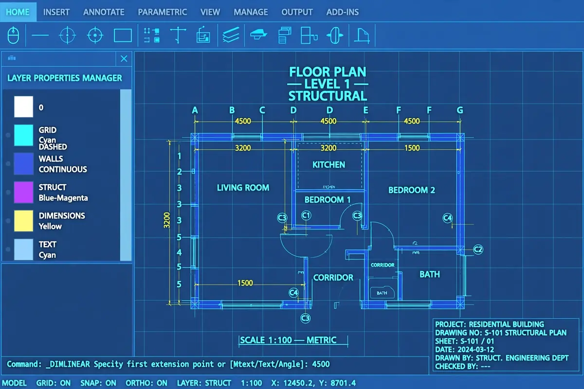
Set up AutoCAD units, drawing limits and layers correctly for structural drawings, with a worked example for a small house plan.
If you have ever opened a structural drawing and found the dimensions reading a thousand times too large, or watched a wall disappear when someone turned a layer off, you have felt what a bad AutoCAD setup does. Units, limits and layers are the three settings that quietly decide whether a drawing is usable or a headache. Get them right once, at the start of the project, and everything downstream — dimensions, plotting, quantity takeoff — falls into place.
This guide walks through the setup I use for structural drawings, in the order I actually do it, and finishes with a worked example for a small house plan so you can check your own numbers against mine.
1. Units: decide what one unit means, before drawing a single line
AutoCAD itself has no idea what a unit is. One drawing unit could be a millimetre, a metre, an inch or a foot — it only means whatever you agree it means. The trouble starts when two people on the same project disagree.
For structural drawings in metric practice, the standard agreement is simple: 1 unit = 1 mm. A 6,000 mm wall is drawn 6,000 units long. This matches how structural engineers dimension in millimetres on site, and it keeps reinforcement bar lengths, cover and spacing in the same numbers the steel fixer will actually measure.
Set it with the UNITS command:
- Type: Decimal
- Precision: 0 decimal places for general arrangement drawings — nobody sets out a column to 0.5 mm on site, and false precision only invites arguments
- Insertion scale: Millimetres, so blocks and Xrefs inserted from other drawings land at the right size
The insertion scale is the setting most people forget. If a colleague's detail was drawn in metres and your insertion scale says millimetres, that detail arrives 1,000 times too small and you will spend an afternoon wondering why the footing looks like a dot.
Imperial drawings and the inch trap
If you work in feet and inches, set Type to Architectural and Insertion scale to Inches. The classic trap is drawing in decimal feet while dimensioning in feet-inches: a 12 ft wall drawn as 12 units is correct, but a 12 ft 6 in wall drawn as 12.6 units is wrong — that is 12 ft 7.2 in. Draw in inches (150 units for 12 ft 6 in) and let AutoCAD format the dimension.
2. Drawing limits: a fence, not a cage
The LIMITS command defines the rectangular area AutoCAD considers your drawing sheet. For structural work, set the limits to the real-world size of the building plus a margin — not to the paper size.
Why? Two reasons. First, the grid becomes useful: with limits set to the building footprint, the grid covers the structure and nothing else, so you can judge scale at a glance. Second, ZOOM All behaves: it frames the building, not a vast empty sheet.
Set the lower-left corner to 0,0 and the upper-right corner to something like the building length plus 10,000 mm on each side. For a 12,000 × 9,000 mm house, limits of 0,0 to 32,000 × 29,000 mm give a comfortable margin and a grid that covers the plot.
One thing limits do not do: they do not stop you drawing outside them. If you need to, you can — AutoCAD will warn but not block. Treat limits as a working boundary for the grid and zoom, and use a proper title block at plot time for the sheet edge.
3. Layers: the filing system of the drawing
Layers are how a structural drawing stays readable when it contains structure, dimensions, notes, grids, reinforcement and a title block all at once. The rule is simple: one kind of information per layer, and never draw on layer 0 except for block geometry.
A practical layer set for a structural general arrangement drawing looks like this:
- S-GRID — grid lines and grid bubbles
- S-COL — columns and walls
- S-BEAM — beams
- S-SLAB — slab outlines and openings
- S-FOOT — footings and foundations
- S-REINF — reinforcement bars and bar marks
- S-DIM — dimensions
- S-TEXT — notes, titles and schedules
- S-HATCH — concrete hatching and section fills
- S-TITLE — title block and border
Give each layer a distinct colour and a sensible lineweight. Structural elements (S-COL, S-BEAM) get a heavier lineweight than dimensions and text, so the structure reads first when the drawing is printed. Keep lineweights in the layer, not overridden object by object — an override on a single line is how a drawing slowly becomes unmaintainable.
Why layer discipline pays off later
Three everyday payoffs. First, freezing S-DIM lets you check the structure without dimension clutter. Second, turning off S-HATCH makes a drawing print cleanly on a small printer. Third, when the quantity surveyor asks for a takeoff, they can isolate S-COL and S-BEAM and measure structure without wading through notes. A drawing that cannot be filtered is a drawing that cannot be checked.
4. Worked example: setting up a small house plan
Take a single-storey house, 12,000 mm long (grid A–D) by 9,000 mm wide (grid 1–3), with a 150 mm thick slab. Here is the setup, step by step, with the numbers to check against.
Step 1 — Units. UNITS command: Type Decimal, Precision 0, Insertion scale Millimetres. Check: a 300 × 300 mm column should be drawn 300 units square. If it measures 0.3 units, your drawing is in metres and the insertion scale is wrong.
Step 2 — Limits. LIMITS command: lower-left 0,0, upper-right 32,000, 29,000. The margin is 10,000 mm on each side of the 12,000 × 9,000 mm building:
- Lower-left margin: 10,000 mm beyond the building on the left and bottom
- Upper-right corner: 12,000 + 10,000 + 10,000 = 32,000 mm in X, 9,000 + 10,000 + 10,000 = 29,000 mm in Y
ZOOM All should now frame the house with comfortable white space around it.
Step 3 — Layers. Create the ten layers listed above. Put the grid lines on S-GRID, the columns on S-COL, and so on. Set the grid spacing to 1,000 mm so one grid square equals one metre on site — a quick visual scale check.
Step 4 — Sanity check with a known dimension. Draw the 12,000 mm long external wall on S-COL, dimension it on S-DIM, and confirm the dimension reads 12000. Then measure the slab: 12,000 × 9,000 mm gives an area of 108 m², and at 150 mm thick the concrete volume is:
Volume = 12.0 × 9.0 × 0.15 = 16.2 m³
If your drawing gives a different volume, the setup is wrong somewhere — usually the units. This single check catches most setup errors before they reach the site.
5. Common mistakes, and how to avoid them
- Drawing in metres, dimensioning in millimetres: pick one and stick to it. Millimetres for structural work.
- Everything on layer 0: the drawing cannot be filtered, frozen or plotted selectively. Move objects to proper layers before issuing.
- Insertion scale left at Unitless: Xrefs and blocks arrive at the wrong size. Set it to Millimetres at the start.
- Limits set to paper size: the grid and ZOOM All stop matching the building. Set limits to the building plus a margin.
- Lineweights overridden per object: keep weight in the layer so a plot style change updates the whole drawing.
6. Saving it as a template
Once the setup is right, save it as a drawing template (.dwt) — units, limits, layers, text styles and dimension styles included. Every new structural drawing then starts from that template instead of from scratch, and every drawing in the project shares the same setup. That consistency is what turns a set of drawings into a proper drawing set: any engineer can open any sheet and know exactly where things are and what the numbers mean.
The setup takes about ten minutes. Fixing a drawing that was started without it takes far longer — and on a live project, it is the kind of rework that is entirely avoidable.
Calculations and engineering guides are for planning and educational reference. Verify final designs against applicable codes with a licensed Professional Engineer.